Behringer Clocked Sequential Control Module 1027
The Behringer Clocked Sequential Control Module 1027 is an authentic reproduction of the original System 2500. Part of the 2500 series it features circuitry from the ’70s that can fit in a standard Eurorack case. You can use it with your existing rig or start your modular synth journey from here. Either way, you’re sure to enjoy using this module. It is easy to install as it fits into a standard Eurorack case. Just connect the power cable to the power supply and screw in the module using the included screws. Whether you’re just getting into modular synths or looking to complete your collection; the Clocked Sequential Control Module 1027 from Behringer is a great tool to have when creating amazing music.
Series 2500
The first 2500 series synth modules came out in the ’70s and tended to be extremely expensive. At the time “all discrete transistor designs” which included some op-amps were very expensive. The discrete circuitry gave the modules a very distinctive sound. They were used by artists such as The Who, Jean Michel Jarre, Vangelis, Kraftwerk and so many more. They provided us with some of the greatest records and film soundtracks we have ever heard.
Sample and Hold
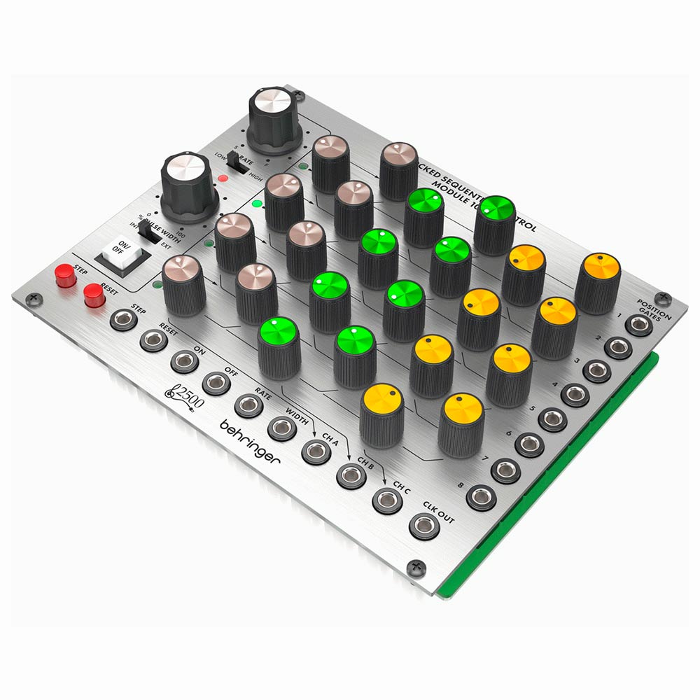
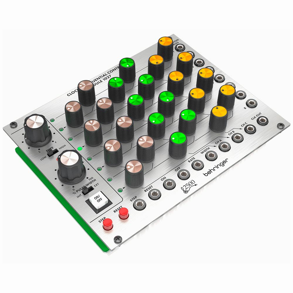
In essence, the Clocked Sequential Control Module 1027 is a classic 8-step 3 channel sequencer. It features an integral 8-step counter with a large rate control knob and low/high range switch. This allows you to set the perfect tempo for your masterpiece. The counter also features a pulse width control and a switch that enables external control for added flexibility. It further includes a large illuminated on/off switch, manual step and reset switches. The 3x sets of 8x colour-coded knobs allow you full control over the 3 CV output voltages to control external VCO frequency (or filter cut off frequency for each step of the sequence).
The Clocked Sequential Control Module 1027 also gives you comprehensive connectivity. The step and reset inputs allow remote control of the step rate and sequencer reset. While the on/off inputs allow other modules to start and stop the sequence. With the rate and width inputs, you have full CV control of step rate and pulse width. Included are 3 sequencer outputs, provided to control any modules of your choice, as well as a clock output from the step counter. And finally, 8 position gate outputs that allow you to trigger other modules from any of the 8 steps.
Sequencer Columns and Position Gates
The front panel offers the main control column provides you with CH A / CH B / CH C Sequencer Columns. You can use the knobs to set the control voltage output for each step. Each column sends out control voltages via that channel’s respective CH A / CH B / CH C output jack. The is an LED strip adjacent to the control column where each LED light indicates its respective sequencer step is active.
On the far right of the Clocked Sequential Control, Module 1027 are the Position Gates. Each of these output jacks sends out a gate signal for its respective sequence step via cables with 3.5 mm TS connectors. These 8 gate output signals are also available via the 12-pin GATE OUT LINK CONNECTOR located on the module underside. This 12-pin connector can connect to and trigger other compatible modules, such as the MIX-SEQUENCER MODULE 1050, via a 12-pin ribbon connector.
Adjustment Controls with the Clocked Sequential Control Module 1027
The RATE knob controls the step speed at which the sequencer moves from step to step. The knob operates in two overall frequency ranges determined by the LOW/HIGH switch. The LOW/HIGH sliding switch sets whether the RATE knob operates in a lower-frequency (LOW) or higher-frequency (HIGH) range. The % PULSE WIDTH selects between width settings for the rectangular waveform ranging from 5% to 95% duty cycle.
The PULSE WIDTH control operates on the CLK OUT jack only, making this control very useful for triggering other modules such as envelope generators, and so on. The INT/EXT switch selects between internal (INT) or external (EXT) pulse width control voltage. When EXT is selected, the % PULSE WIDTH control knob is disabled. The ON /OFF button starts or stops the sequence with a manual button push. The STEP button allows you to manually progress to the next sequencer step. Finally, the RESET button allows you to manually restart the sequence at step 1.
Inputs & Outputs
The Clocked Sequential Control Module 1027 also features 6x Inputs and 4x Outputs on the bottom of the module. The STEP jack routes external trigger signals for the STEP button into the module. The RESET jack routes external trigger signals for the RESET button into the module. ON jack routes external trigger signals to enable the step counter into the module. The OFF jack will route external trigger signals to disable the step counter into the module.
The RATE jack will route in external control voltage signals for the sequencer’s step speed (usually controlled by the RATE knob). The WIDTH jack allows for control voltage and modulation signals for the rectangular waveform. The CH A jack sends out control voltage signals for the CH A sequencer column. CH B ack sends out control voltage signals for the CH B sequencer column. CH C jack sends out control voltage signals for the CH C sequencer column. Finally, the CLK OUT jack exports the internally generated clock signal. The internal clock produces a gate pulse every time the sequencer steps, and the gate pulse’s width can be adjusted using the % PULSE WIDTH control or via the WIDTH control jack. All these jack functions are connected via cables with 3.5 mm TS connectors.
DJ City also offers a wide range of additional Eurorack Modules that can be combined with the Clocked Sequential Control Module 1027.


